Acoustic borehole locator LAS
Appointment
The borehole acoustic locator LAS is designed to determine the volume of underground reservoirs at underground gas storage facilities.
LAS can be used in the construction of underground storage of hydrocarbons and toxic waste of various industries, in the extraction of mineral salts by leaching, the study of deep karst and other similar problems.
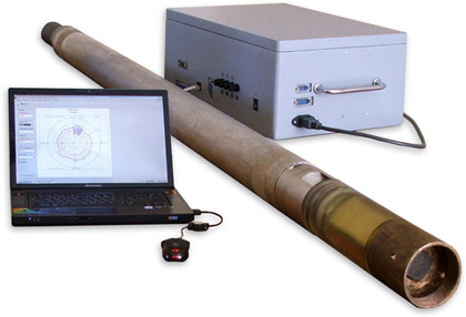
The borehole acoustic locator LAS is registered in the State Register of Measuring Instruments of the Russian Federation under No. 61834-15. Certificate of type approval of measuring instruments RU.C.27.002.A No. 60045 issued by the Federal Agency for Technical Regulation and Metrology.
The declaration of conformity of the Customs Union TC N RU D-RU.AG35.B.00341.
Permission to use No. РРС 00-049893 is issued by the Federal Service for Ecological, Technological and Nuclear Supervision.
General information
-
The LAS complex consists of an ultrasonic scanning locator made in the form of a downhole tool (PS), a ground telemetric unit (BNT), a laptop and is equipped with technological software (TPO) and a data processing program (AML).
-
The equipment was created on the basis of the latest technologies for receiving and digital signal processing using a modern elemental base and original circuitry solutions.
-
PS performs a slice scan of the cavity and determines the speed of ultrasound in the working environment. The PS is equipped with a high-speed analog-to-digital converter, large RAM and a powerful special processor that organizes the work of the locator in all modes.
-
The digital data transmission channel between the PS and BNT allows to increase the dynamic range, resolution and accuracy of the equipment, and also provides its maximum noise immunity.
-
BNT organizes two-way flows of commands between the hardware elements of the LAS complex and generates arrays of scan data, linking slices in magnetic azimuth and depth.
-
TPO implements all the algorithms of the LAS complex and has a convenient operator user interface. Data during the location process is displayed in the form of a polar scan attached to the magnetic meridian of the contour of the horizontal section of the cavity or in the form of an oscillogram.
-
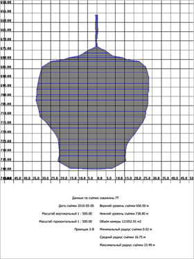
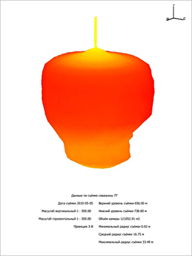
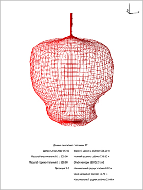
AML carries out all the procedures for analyzing the acoustic sounding data of the studied objects and presents the results in the form of: polar scan of the contour at a given depth, vertical sections, 3-dimensional image of the cavity, table of slices, graph of volume dependence on depth.
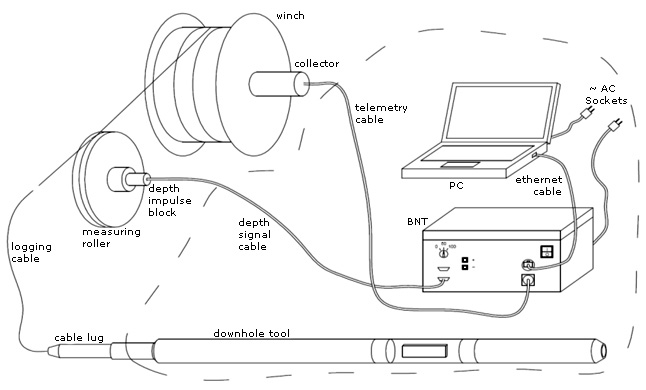
LAS connection diagram
General view of the complex prepared for work, together with the equipment of a geophysical elevator.
Technical characteristics of the complex
|
Name |
Value |
|
Range of measured distances: |
|
|
The accuracy of determining distances,% |
2 |
|
The error in determining the angle of rotation of the speaker system relative to the direction to the north, ang . hail. |
5 |
|
Location carrier frequency, KHz |
298 |
|
Ultrasound pulse width setting range, μs |
from 3 to 850 |
|
The range of the amplitude setting is the voltage at the antenna upon excitation of an ultrasound pulse, V |
from 1 to 300 |
|
Scan time of one cut, s |
160 |
|
The minimum angular step during scanning, ° |
1 |
|
Length of a three-core logging cable of the KG3-60-150 type, m |
up to 5000 |
|
Ground Recording Unit Parameters |
|
|
Supply voltage of alternating current 50 Hz, V |
220 ± 10% |
|
Maximum power consumption from AC 220 V, W |
300 |
|
Computer Communication Interface |
Ethernet |
|
Operating temperature range, ° С |
from 10 to 50 |
|
Overall dimensions, mm |
430 x 330 x 180 |
|
Mass of the registering unit, kg, no more |
eleven |
|
Downhole Scan Probe Parameters |
|
|
Maximum hydrostatic pressure, MPa |
20 |
|
Operating temperature range, ° С |
from 10 to 80 |
|
Diameter of the downhole tool, mm |
80 |
|
Downhole tool length, mm |
2150 |
|
Weight of the downhole tool, kg, no more |
25 |
Working windows example
- Processing software: cross-section table and 3-dimensional well model.
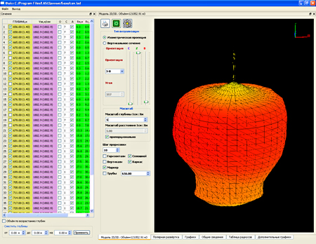
- Processing software: a table of sections and a 3-dimensional model of the well (horizontal and vertical sections).
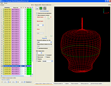
- Processing software: sectional table and 3-dimensional well model (horizontal sections only).
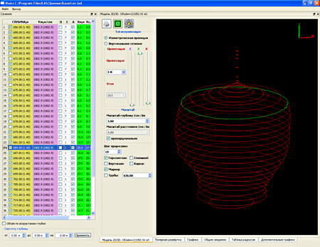
- Processing software: cross-section table and 3-dimensional well model (only vertical sections).
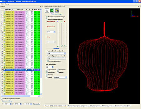
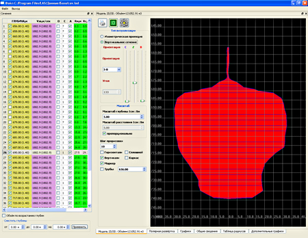
- Processing software: cross-section table and 2-dimensional model of the well (vertical section, direction west – east).
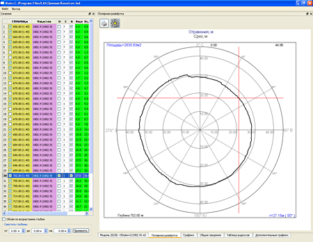
- Processing software: section table and section scan in the polar coordinate system.
- Processing software: table of sections and graphs: capacitance, speed of sound, vertical profile in one of the azimuthal directions.
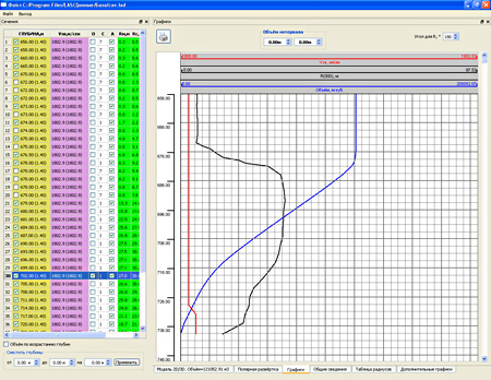
- Processing software: a table of sections and a table of the main parameters of the well.
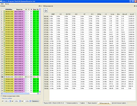
- Processing software: one of the possible combinations of windows when working with a program for processing scanning results.
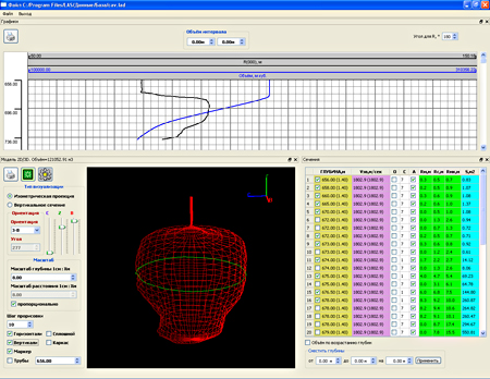
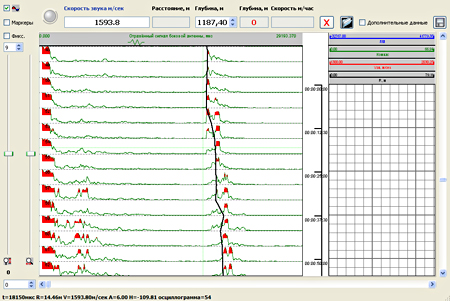
- Technological software: scanning in the registration mode of the arrival time of the reflected signal.
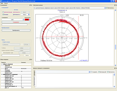
- Technological software: scanning in the mode of full registration of the reflected signal.
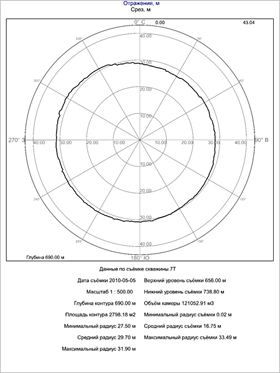
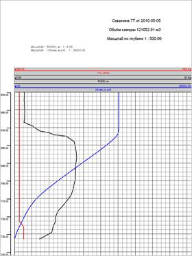
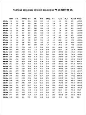
- Printout of scan results from the processing program.
Look:
Presentation LAS [Presentation_LAS.pdf]
SP 34-106-98 Underground storage of gas, oil and products of their processing
Work on the well (photo report)
A version of the station of the LAS complex and the lift based on the GAZelle vehicle

